1.15 (0.606 dB) in vertical or horizontal position
0.55 (-2.59 dB) in slant configuration (45° angle)
Power gain:
H & V: 5.07 (7.05 dB)
Slant: 2.53 (4.03 dB)
Impedance:
50 Ω
VSWR:
< 1.28:1
Polarization:
Vertical, horizontal, or slant (45 ° ) polarization or custom H/V ratios.
Maximum input power:
5 kW per element, rated at power divider handling for multiple levels
Input connector:
7/8" EIA for single element, 1 5/8" or 3 1/8" EIA on power divider for multiple element arrays.
Standard Mounting:
Designed to attach to a customer-supplied 1-1/4" pipe (1.5" OD) - 3" pipe (3.50" OD) or similar tower leg. Standard mount has positioning built in for vertical, horizontal and slant (45°) mounting.
Includes downward support tension device for added support over the length of antenna.
Also includes anti-rotation arm kit to attach to tower.
Custom mounts:
Option for up to 5-1/4" leg diameter available at additional cost - contact factory.
Options:
-Full or 1/2 Wave Spaced
-Input Size Designed for TPO
-Directional Patterns
-Radome
-Adapters
Model 6025 Antenna Weight & Windload and dimensions
1 element
-Windload -
ft2
m2
Without ice, Rev G
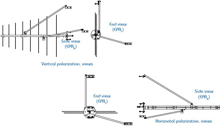
Vertical elements
EPAN
5.52
0.51
EPAT
2.63
0.24
Without ice, Rev G
Horizontal elements
EPAN
5.95
0.55
EPAT
2.69
0.25
- Weight -
lb
kg
Without ice
80
36.3
Shipping, standard kit
110
50
- Size -
ft
m
Radiation Aperture (vertical)
26
4.9
Physical space used
6
1.9
Recommended pipe length
8
3.64
Notes:
WINDLOAD TABLE(S)
1. Antenna radiation aperture is the distance from the center of the top bay to the center of the bottom bay. Five feet (1.5 m) of the pipe is required above the top of the top bay and below the bottom bay. Total tower space recommended allows ten feet (3 m) of clear tower space above the center line of the top bay and below the center line of the bottom bay, to protect from pattern interference by other antennas. At frequencies lower than 98 MHz, each of these dimensions will increase by up to 1 foot (0.3 m) per bay.
2. Windload and weight tabulations assume full-wave bay spacing and include the bay, mounts and interbay feedline.
3. Antenna areas and weights calculated in accordance with TIA-222-G. EPA(N) – Effective projected area associated with the windward face normal to the azimuth of the antenna: EPA(N) = (Ca AA )N EPA(T) – Effective projected area associated with the windward face at the side of the antenna: EPA(T) = (Ca AA )T Assumptions: Structure Class II; Exposure category C; Topographic category 1; Maximum basic windspeed 90 mph; with 1/2 inch design ice, 40 mph; Maximum height above ground 200 ft.
4. Ask for technical assistance at Shively if you are planning to mount antennas on AM towers or install them at altitudes over 3,000 ft (915 m) above mean sea level.
Typical Elevation Patterns
These patterns are based on 98.1 MHz, no beam tilt, no null fill. Contact factory for your customized elevation pattern
6025 Elevation Patterns Full Wave
Contact Factory for Elevation Pattern
Sample Azimuth Patterns for Shively Series 6025 FM Antenna
NOTE: Model 6025 is a directional antenna.


Reviews
There are no reviews yet.